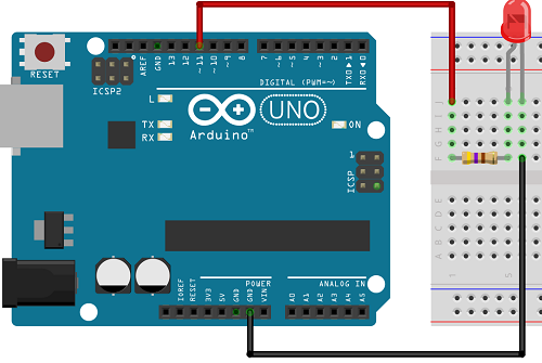
Using and Understanding Breadboards
One of the simplest control circuits is the blinking LED. When
testing this circuit, it is often necessary to use a different size resistor.
It is possible to use Ohm's Law to calculate the size of the resistor, but it is
faster to just try the circuit before the final construction. Patented
quite recently ( in the 1970s ) the solderless breadboard is used to test a
circuit. It was an important technological development as was protected by
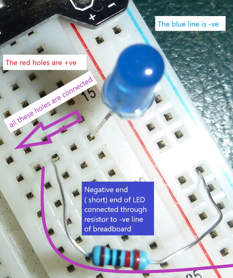
patents. The holes in a breadboard are interconnected, and allow each component
of the circuit to be connected to the complete circuit. Please read this week's
Tasks and Activities.
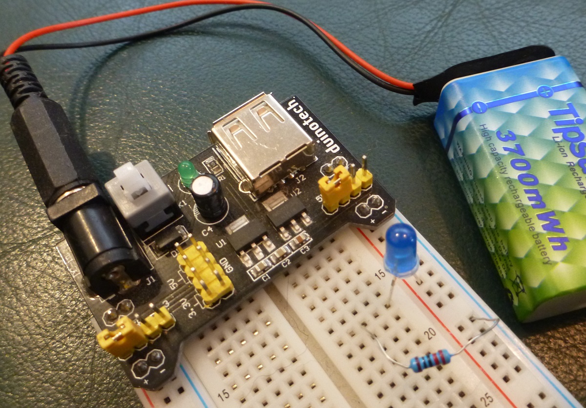
- Put together your breadboard, LED and a resistor and make it
glow!
- Use a multimeter ( borrowed from the front desk ) to test the
size of your resistor. How does the brightness of the LED
change with the size ( Ohms ) of the resistor?
- Why are breadboards use to develop prototype circuits?
- What other prototyping tools are used to test a circuit
before it is assembled? ( Hint -- Look at
this website
)
|
|
|
Don't forget to email your choices/answers
to Mr. Widmer by the end of this week. Keep a copy of that email
in your Google Docs folder.
|
|